Shoreham’s Radar Station: RAF Truleigh Hill
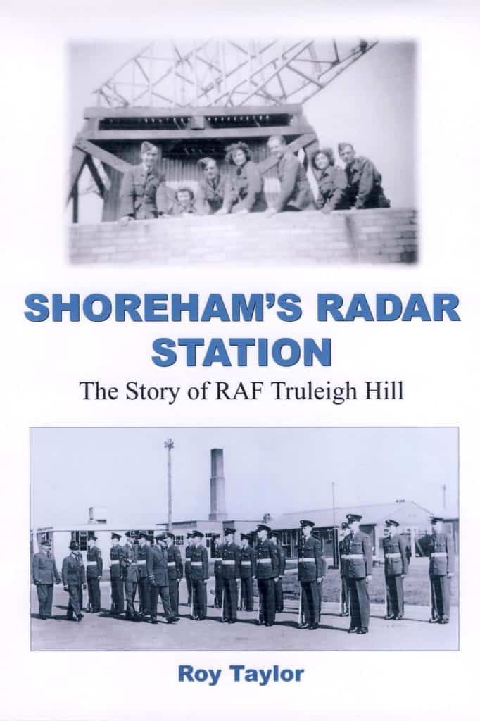
This is the full story of Shoreham’s Radar Station: RAF Truleigh Hill as researched and written by Roy Taylor. This 110 page book was written in 2007 and then updated in 2008. It offers a fascinating insight into the technology and operation of the RAF Truleigh Hill ROTOR Radar station. Likewise it opens the doors on the life at RAF Truleigh Hill Camp in Stoney Lane, built to support the Radar operations. The book comprehensively covers the sites and the personnel posted there. Click the book cover to open. Hard copies are available from the author.
There is additional technical information about the Truleigh Hill site in an article written by Sqn Ldr T Howard Toon. His research was published online in 1998 but has long since been lost. An archive/backup of his article can be found here. We have transcribed the text and images below. ©1998 TH Toon
An Outline History of the
Radar and Radio Installations
at Truleigh Hill, West Sussex
Sqn Ldr T Howard Toon
BA CertEd MBCS CISP RAFVR(T)
World War Two – The Chain Home Low Radar
In the 1930s the government were growing more worried about the situation developing in Europe and decided that some form of warning system was needed as part of the defence of this country.
Fortunately, as a result of some pioneering work by Hülsmeyer (Germany), and Marconi (Italy) the idea of using the reflection of radio waves to determine the location of distant objects was already being investigated. Appleton had used radio echoes to determine the height of the ionosphere in 1924 and Hülsmeyer had actually proposed a system for ships to use radio waves as a collision avoidance system. Many other scientists were carrying out similar experiments around the world so radar, as such, had many independent births.
In the mid 1930s H E Wimperis of the Air Ministry asked Robert Watson-Watt, superintendent of a radio department at the National Physical Laboratory, if some form of ‘death ray’ was possible using a radio beam to disable remote targets.
This was rejected as being unrealistic but Watson-Watt prepared a report, drafted with the assistance of Arnold Wilkins, in February 1935 entitled ‘The Radio Detection of Aircraft by Radio Methods’.
This report was accepted by Sir Henry Tizard’s scientific committee and an experiment was carried out near Daventry on February 26th 1935. The BBC’s short wave transmitter at Daventry was used to detect a Heyford bomber at ranges up to 8 miles and heights of up to 6,000 feet.
Even though the experimenters knew what to look for, and the aircraft is rumoured to have been trailing a length of wire ideally cut to act as a radio reflector on the frequency being used, the experiment was considered to be a great success and the system underwent rapid development to become the UK’s first radar early-warning system.
By 1939 a chain of Air Ministry Experimental Station (AMES) Type 1 Radar Stations along the south and east coasts of Britain had been established to detect aggressors in the air or at sea.
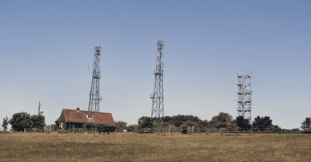
The new installations were typified by a set of four high wooden towers supporting fixed aerials acting as a transmitter station and four nearby smaller towers acting as a receiver site. These formed the ‘Chain Home’ (CH) system.
The CH transmitters acted like radio floodlights and the receiving aerials were made up of pairs of dipoles at right angles to each other. A device controlled by the operators, called a goniometer, tuned the signals from the dipoles and displayed the result on a cathode ray tube trace. This gave the operator the direction and distance to the target but the accuracy was subject to many outside influences. By switching to alternate pairs of dipoles the height could also be calculated. Only aircraft at fairly high altitudes could be tracked by this method, however, and low-flying aircraft or surface shipping could not be detected.
To overcome the problem of detecting the lower targets, a second chain, more or less alternating with the first and integrated into the same reporting system, was created and known as the ‘Chain Home, Low’ (CHL). The radars were based on the Coastal Defence radars used by the Army and one of the sites chosen was on top of Truleigh Hill and work began in 1939 to install an AMES Type 2 radar there.
This Chain Home Low station consisted of two separate aerials, one for the transmitter and one for the receiver, mounted on 20 foot high gantries, with the equipment housed in a hut underneath each gantry. Since CHL operated on a wavelength of 1.5 metres the aerials were short enough that the arrays could be rotated, which was done manually by an operator using cranks and a chain-driven system from inside the hut. The operators had to synchronise both aerials but the result was a beam about 25° wide, rather than the floodlight effect of CH.
The aerials were not continuously rotated but, instead, were aimed at the target and moved from side to side to get the best reading. The received echo was displayed on a single trace on a cathode-ray tube.
This display gave slant range to target only. Information about possible targets, detected at fairly long range by CH, could be passed to the CHL for tracking at lower levels as well as the CHL feeding information back through the CH stations to the filter rooms. It was not until well after the Battle of Britain that power turned, single arrays (which combined transmitting and receiving aerials) were introduced.
These motorised aerials rotated constantly and gave a continuous reading. This new system also allowed the target to be more accurately detected and allowed multiple targets to be tracked on a single display.
When the new cathode ray tube equipment known as Plan Position Indicator (PPI) was introduced the result was a stunning advance.
The PPI displayed the beam as a rotating line, much as modern radars do, and targets could now be clearly seen in two dimensions. Height was still not given but the operators became very skilful at estimating height from the reflections given by known targets and the signal strength.
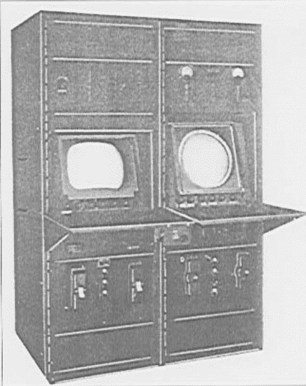
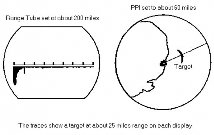
The operator’s console now consisted of two cathode-ray tubes side by side. the left-hand display was the old single trace with range to target shown as a ‘blip’ on the line. The right-hand display was the new PPI. In normal use the left-hand display would be set to about 100 miles full scale and the PPI would be set at about half this range. Between the two, excellent coverage was achieved.
The main search direction was out towards the English Channel where the risk was seen to be greatest and the equipment installed was capable of spotting low-flying aircraft at ranges up to about 50 miles.
Information from the radar was initially interpreted in the buildings at ground level below and details were passed to the nearby CH station at Poling. The CHL radar could detect aircraft flying at 500 feet at ranges of up to 30 miles and higher aircraft could be tracked at up to 100 miles. This meant that CHL radars could be used for medium as well as low-level coverage and thus more than filled the gaps left by the CH systems. The importance of these radar systems during the Battle of Britain is hard to over-estimate. Without them the Royal Air Force would almost certainly have lost the battle. The early warning provided by CHL radars enabled the RAF to intercept incoming aircraft which would otherwise not have been detected until they were within visual range. In this case, fighters would not have had sufficient time to reach the bombers before they had attacked their target. The only alternative would have been to mount standing patrols of aircraft in the path of likely attacks but the severe shortage pilots and aircraft in 1940 would have made such tactics infeasible.
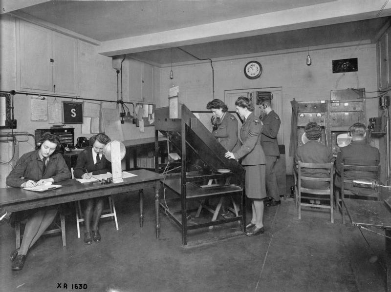
At Poling the information from Truleigh was combined with that from their own CH radar and the interpreted results were passed on to the main ‘Filter Room’ at Stanmore.
This extended reporting system slowed down information being passed to Fighter Command but was designed to overcome the inaccuracies in the range and height measurements being interpreted as multiple targets. In fact, due to the dedication and very high skill levels of the operators, it proved to be an extremely successful and efficient system throughout the war and was critical to the success of the whole system.
Towards the end of the war, as hostilities were confined to the Continental arena, Truleigh Hill and its like were no longer seen to be of any great value and they were run down. Many of the CH, CHL and other sites were simply gutted and abandoned, others were vandalised. Some were put under ‘care and maintenance’ but a lack of manpower, or even a real interest in them, led to most of these also becoming run down.
This period was short-lived however, as a new threat was perceived to exist to the East of Europe. The Soviets first successful atomic bomb test and the subsequent ‘Cold War’ led to massive development programs in the UK defence system and Truleigh Hill was part of the system.
Radio Aids to Aircraft – Gee
Truleigh Hill was given a new role towards the end of the war. Even as its value a CHL radar site declined, a new development in radio navigation was becoming important.
The development of radio beams as a navigation aid to distant aircraft had been used to great advantage by both the Luftwaffe and the RAF. By transmitting signals from two or more ground stations, aircraft receiving the signals could calculate their position with a reasonably high degree of accuracy. The British developed ‘Gee’ was one such system and Truleigh Hill was chosen to be part of a ‘Gee Chain’.
The Gee system is basically quite simple but requires very accurate equipment both on the ground and on board the aircraft. A ‘Master Station’ transmits a fixed-length radio pulse on a frequency that will give good reception at long range. This signal is also received by a second, ‘Slave’, station. The slave station in turn transmits another fixed length pulse a specified time after receipt of the original and another slave station does likewise after yet another specified delay. Most chains used a third slave to give greater accuracy still.
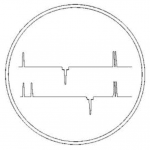
An aircraft using the system receives the three signals and they are displayed as ‘blips’ on two traces on a cathode-ray tube. The screen was also marked with a graduated scale and the actual time between the pulses could thus be measured. Since the transmission intervals were known, the position of the aircraft could be calculated from the measurements of the actual delays. This relative timing had to be maintained with great accuracy for the system to work properly.
The operators had to concentrate on what must have been a very tedious job with little glory or recognition yet they did so with great dedication and skill throughout the time that Gee was in use. Operators who worked the system took enormous pride in their achievements and many of them spent a great deal of their, otherwise free, time carrying out improvements, re-wiring etc, that was not strictly their responsibility but which led to a more efficient and dependable system. The three chains were controlled by HQ No 90 Group and overlapped and extended (at 10,000 feet) well into northern France. The following table summarises the three chains. Grade ‘A’ means continuously operational; Grade ‘B’ is operational on stand-by arrays; Grade ‘C’ is on maintenance or test and may transmit for test but must not be used; Grade ‘D’ means forbidden to transmit. The identification was achieved by ‘ghost pulse blinks’ from the master station.
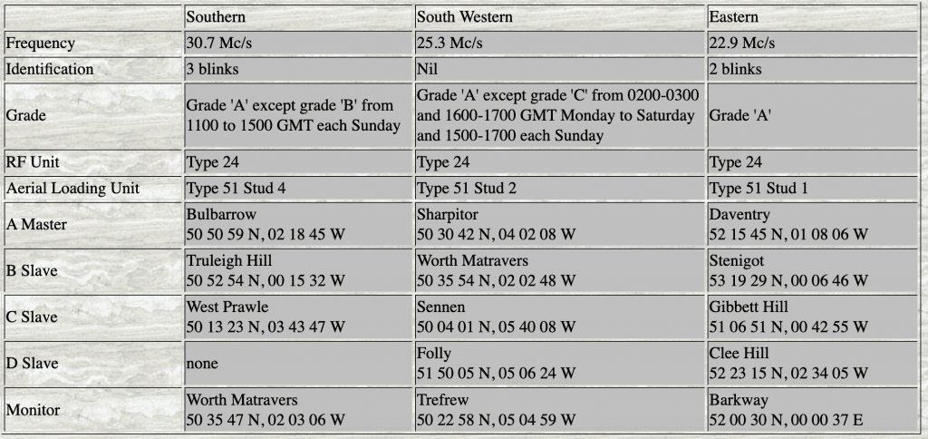
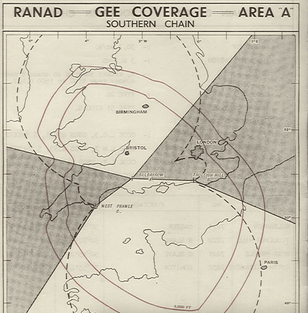
At this time the Southern chain was significantly weakened by the lack of a third slave even though the ‘5 mile accuracy’ line extended well into central France. There were large areas to the east and west of England that lacked sufficient cover but these were covered by the other two chains.
This system remained in action for some time after the war and was operated by ‘National Service’ men and women then later by civilian engineers before finally closing down in 1952.
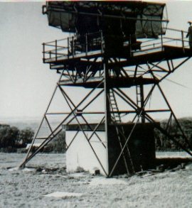
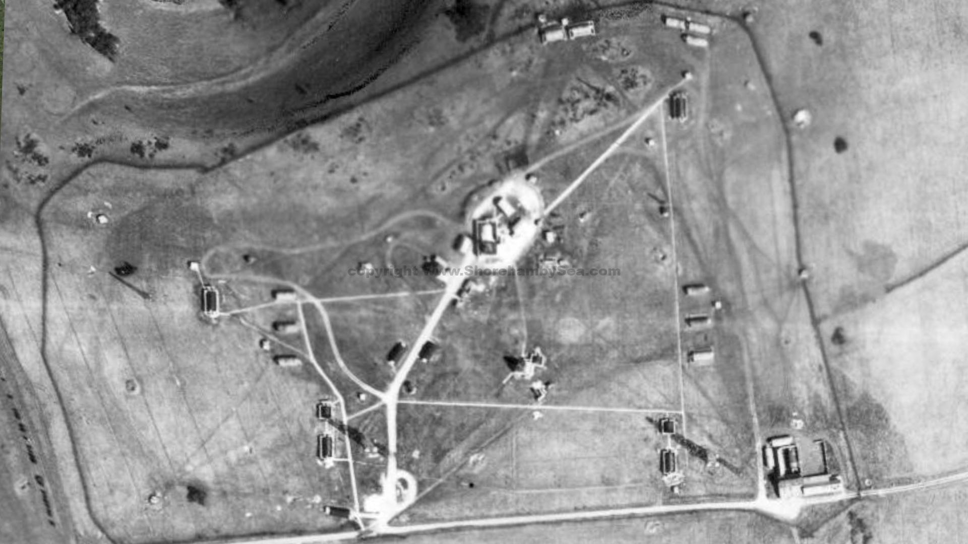
The Gee site at Truleigh Hill consisted of two receiver sites, at the North-west and North-east corners of the site, and two transmitter sites, at the South-west and South-east corners. Each receiver site consisted of a wooden tower 70 or 80 feet high carrying the aerial and a Nissen hut, housing two receivers, inside blast-walls at ground level. Each transmitter site had a wooden tower, one 90 and the other 120 feet high, carrying the aerial and a Nissen hut housing two transmitters, also inside blast-walls at ground level. Each transmitter site also had a generator shed (Nissen hut inside blast walls) housing two Lister diesel generators. The receivers and their masts were interlinked by underground cables which also carried signals to the transmitters. Similarly, the transmitters and masts were interlinked by ‘box-feeder’ cables carried on wooden posts about 10 feet high.
The importance of the overall installation may be judged from the built-in redundancy. Not only was each site duplicated, but within each site so was the equipment. In the event, the operators at Truleigh Hill found that they never had to use most of the backups and any one of the duplicated systems was dependable enough, throughout the life of the station.
Rotor
After the Second World War perceptions changed very rapidly. Russia came to be seen as a very real threat and there was every reason to believe that a ‘Third World War’ was a very high possibility.
There was much political posturing by all sides as countries rebuilt their economies and established new spheres of influence. The development of atomic weapons by the Russians and their ability to deliver them using long range TU-4 bombers alarmed the government of the day. Many studies were carried out as to the likely result of a nuclear exchange with casualty rates predicted at anywhere from 5% to 95%. Most informed opinion seems to have settled on a 50% to 90% casualty rate and this led the government to begin planning for this possible Third World War.
In order to give as much warning as possible to the UK it was decided that a new chain of radar stations would be needed. The decision was made re-use what already existed and upgrade as much of the older radar equipment as possible. The Chain Home stations were refurbished as a matter of top priority and some of the old CHL stations were redeveloped as Chain Home Extra Low (CHEL) sites to, once again, fill in the low level gaps in the CH system.
This was done as a matter of top priority and the equipment was installed at some 66 sites round the country. The sites were also hardened significantly to offer the operators protection from a near-hit with a 20-Kiloton Atomic Bomb, a standard Soviet weapon at that time. This meant that the buildings would have to be constructed from reinforced concrete 10 to 14 feet thick all round and, for additional protection, be buried underground. A hierarchy of sites was established with single level bunkers in the front line feeding their information back to larger, two-level bunkers which in turn fed information to the larger control sites up to three levels deep. On the eastern and southern sites the bunkers were usually underground while the western and many more northerly sites were fortified above ground level.
Truleigh became a single-level R2 site as part of the ROTOR system and in the underground bunker a team of RAF personnel worked at plotting tables and communications equipment not all that different from during WW2.
The regular RAF were always short of trained personnel however so they were supplemented at various times by others. Civilian technicians directly employed by the Ministry of Works were used to maintain the main electrical power supply and the bunker’s internal electrical equipment. National Service conscripts were also used in a number of jobs and, in 1953, a local volunteer force was recruited.
The Royal Auxiliary Air Force opened No 3701 (County of Sussex) Radar Reporting Unit based in Brighton. There were only two such RRUs set up and the volunteers underwent evening and weekend training augmented by annual camps at RAF and other establishments. As well as an annual bounty of £15 the members of 3701 RRU were paid between 2/6d and 4/- (depending on rank) for a two-hour training period. On camps they also received normal pay and allowances. 3701 RRU adopted the motto “Alert the Eagles” and were affiliated with Wartling, Beachey Head, Truleigh Hill and Poling during their existence.
In spite of the promises made in the recruiting booklet there was never much hands-on training given and the evening visits to Truleigh Hill were often a disappointment since the regular duty team only worked a day shift normally and were not well pleased at having to stay on for the RRU training. The promised opportunity to take over the station and operate it one Sunday each month never materialised on a regular basis either. An exception to this was a period of about 5 weeks during the Suez crisis of 1956. This situation was taken so seriously that the RRU were operating almost every evening and weekend and a supply of small arms were placed on racks inside the entrance tunnel in case of special forces being landed nearby to disable the radars. In addition, local TA units were placed on stand-by and worked with the RRU as a defence force. 3701 RRU was disbanded in 1958 when Truleigh Hill and its kind became redundant.
Television
In the early 1950’s television was still in its infancy. With the coming of the Coronation of Her Majesty, Queen Elizabeth the Second on June 2nd 1953, however, interest mushroomed. There were severe restrictions on capital investment at this time so no new transmitters were available for the coronation. Instead, the BBC were given permission to install three temporary, low power stations to serve the Brighton, Newcastle and Belfast areas.
The Brighton transmitter was at Truleigh Hill and used the wooden RAF mast at the south-east corner of the site. The transmitters were converted RCA type ET 4336 units mounted on a converted outside broadcast trailer. This equipment was modified from its original HF power of 250w to give a peak white power of 500w in band 1. The vision transmitters used a new grid-modulated rf stage with a BBC designed stabilising amplifier as the modulator. A new rf stage was added to the sound transmitters and the conversion, production and installation of the whole system was completed in only three months jointly by the Designs and the Planning & Installation Departments. The transmitter went into service on May 9th 1953 using channel 3 and simple dipole aerials to transmit. The receiver system consisted of four inverted ‘V’ aerials to receive the signals from Alexandra Palace.
Truleigh Hill was eventually meant to be replaced by a new transmitter built at Rowbridge Farm near Newport on the Isle of Wight but this proved to be unsatisfactory for reception in the Brighton area. Truleigh was, therefore, retained but since Rowbridge was working on channel 3 Truleigh had to be moved onto channel 2 to avoid interference.
The haste in which this link was erected, and the extended period for which it was kept in use led to a few minor problems on site including the aerials being damaged in high winds. The Gee engineers usually did the running repairs since they were already on site but, in spite of these problems, the relay was a continued success and was finally removed in 1957 when other, more permanent, local repeaters were constructed.
1998 Exploration of the site
The Bungalow
Entry to the new, underground installation was through a guardhouse built to look like a bungalow. Examples of similar bunkers are seen at many locations round the country and a particularly fine example is open to the public at Kelvedon Hatch.
The Truleigh Hill bungalow was completed in 1952, shortly after the death of the King. Even while it was being built equipment was being lowered into the tunnel by crane then taken along the tunnel to the bunker for installation. Once completed, the only access to the tunnel was through the front door and the guardroom or through the steel plant access doors at the rear.
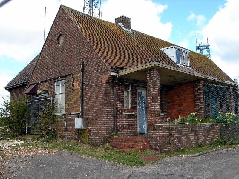
The bungalow was actually a reinforced building capable of withstanding significant blast effects. The normal entrance would have been through the front door and into the guardroom but there were also alternative access points at the rear. Some idea of the original degree of protection may be had by examining the windows. The brickwork is backed by concrete and steel shutters which remain from the original use. The ceiling of the ground floor is a reinforce concrete slab which supported the water supply storage tanks for the installation. Water was supplied from the northern side of the hill by two pumps at Hortons Corner.
When the levels in the bungalow tanks fell, the pumps would cut in automatically and force water up the hill through a pipeline with two non-return valves. The supply had two separate feeds so that the load could be spread – the pumps were quite capable of drawing enough water to deplete supplies to a significant area of housing otherwise. The excavation for the bunker was done by a single digger which gradually dug itself into the ground and created a hole some 60 feet deep. The spoil was removed by a fleet of trucks many of which, the drivers were paid by the load, actually drove down the steep northern side of the hill rather than go the long way through Shoreham. rather aptly, a number of the dangerous driving scenes from the 1957 film ‘Hell Drivers’ (Stanley Baker, Patrick MacGoohan, Herbert Lom, Sid James etc) were filmed along the roadway from Truleigh Hill to the corner on top of Beeding Hill.
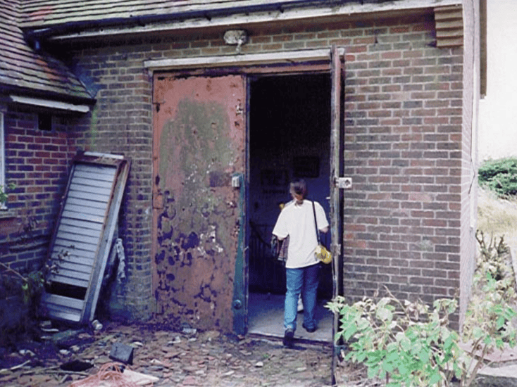
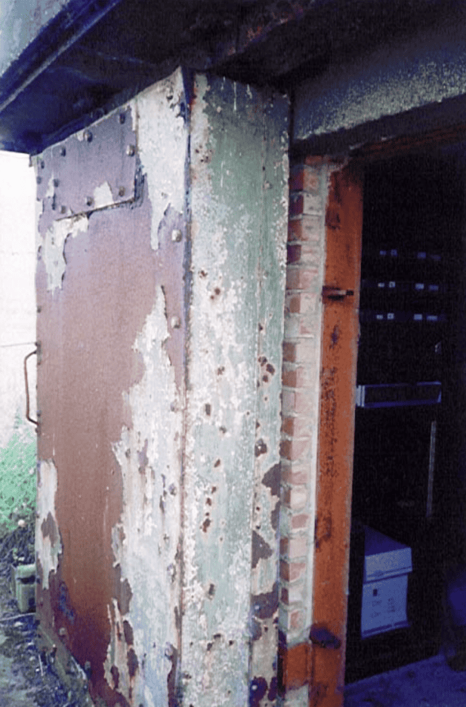
At the back of the bungalow can be seen the larger doors used when equipment, rather than people, had to gain access. Steel doors lead to the same staircase as the front door but are wide enough to allow for plant equipment to be brought in. The shutter on the wall to the right covers another access port which is protected by a sliding steel door on the inside. All access to the staircase is now sealed off except via these steel doors. (sic see Roy Taylor’s book for detail of the tunnel position underground).
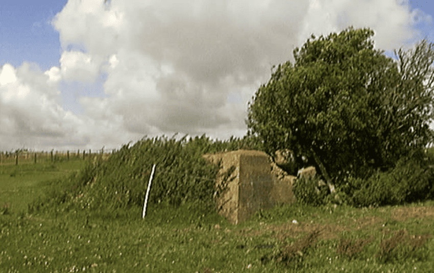
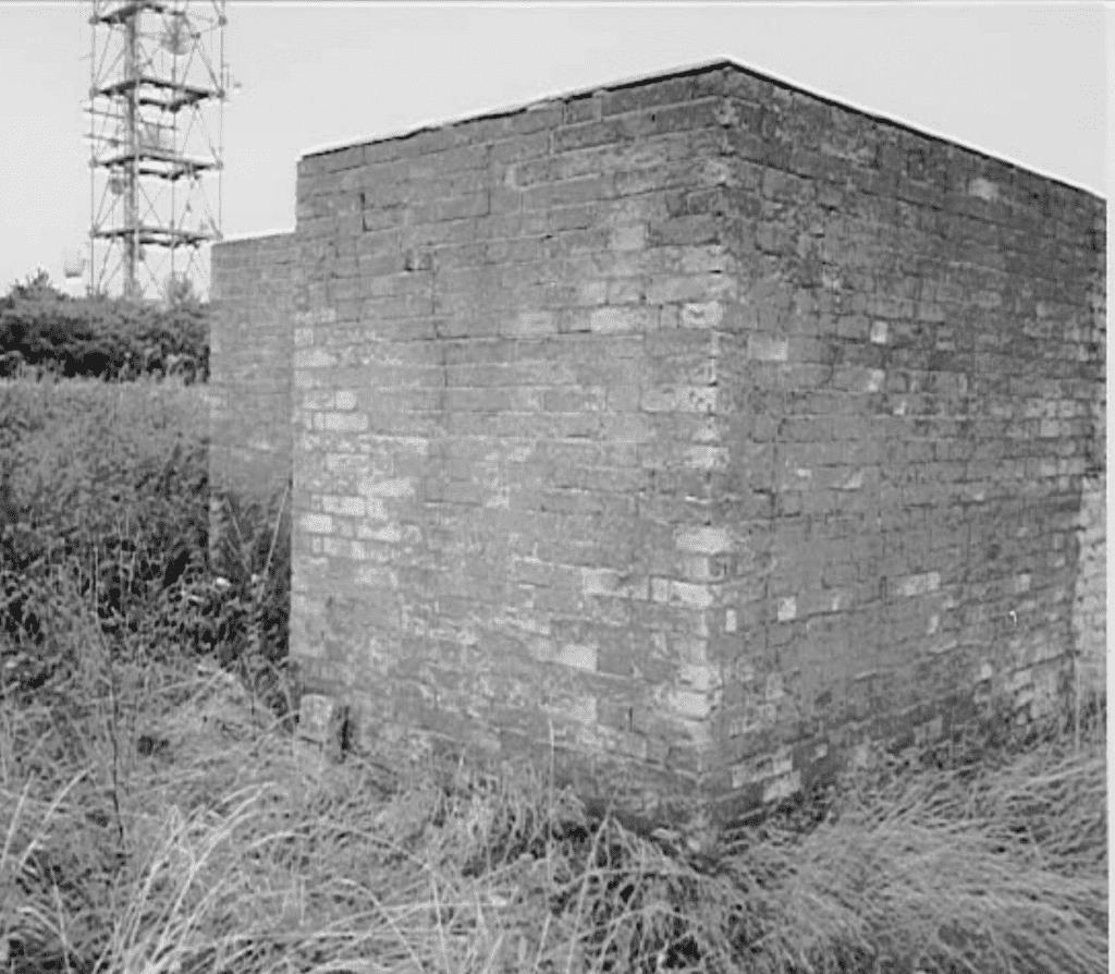
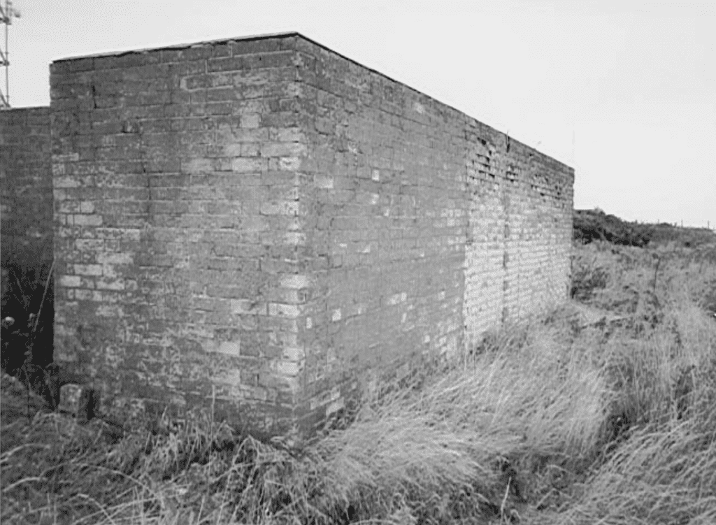
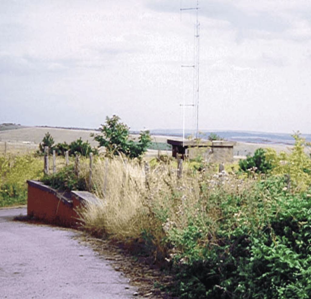
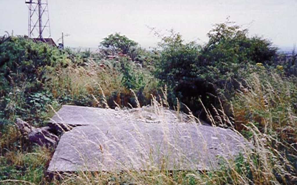
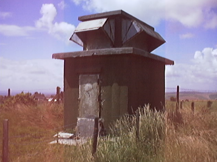
Surface Blockhouse
Above ground and near the the cable duct entry point is a very strong blockhouse with a couple of small radio masts fixed to it. The masts are a recent addition and carry traffic for local companies. The whole building is obviously designed to withstand a great deal of punishment and the roof is re-inforced concrete. latest investigations seem to indicate that the radar head would have been on top of this roof and would have been part of a Type 14 installation.
It is thought that the building itself once housed part of the radar aerial control gear for the Type 14 and anything inside would certainly have been well protected. The door to this building is a massive steel and concrete construction that runs on rails at the top and bottom and the whole is obviously designed to be massively strong. There are four steel feet bedded in concrete just beyond the corners of the building. These were originally assumed to be the feet of a gantry helping to support a radar array but there is no evidence for this assumption. They may even be a remnant from the earlier CHL station and the concrete base might have been re-used for the new radar. Some of them have been used for staying more recently installed masts.
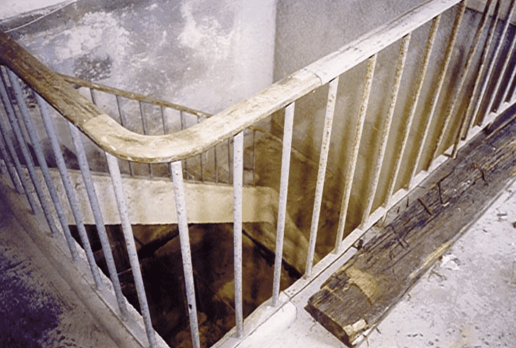
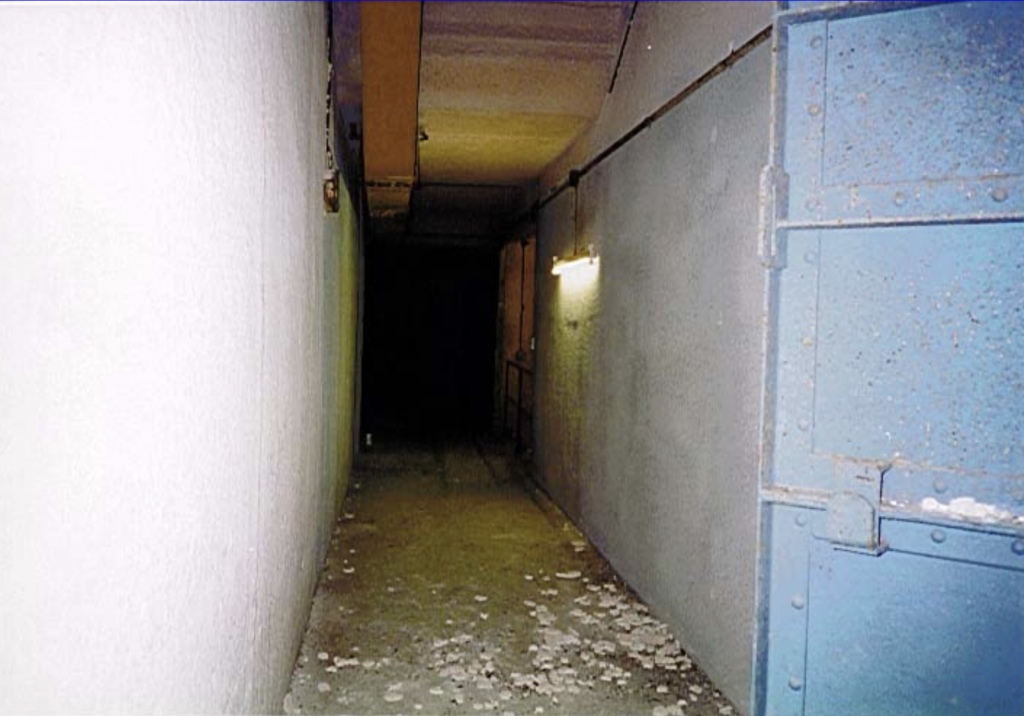
The Tunnel
At the bottom of the staircase is the tunnel. The doors here are steel panels but are not believed to be original equipment they were probably added just prior to the site being sold off as surplus to military requirements or as a deterrent to intruders while the site was awaiting sale.
Even after more than 40 years, the tunnel is still dry and a pleasant, cool, temperature is maintained naturally throughout. The floor would once have been immaculately polished but the National Servicemen responsible for this finish have long since departed. The tunnel is about 100 yards long and slopes gently down into the hill. Cable ties are fixed all along the tunnel and mains electricity was laid in all the way from the Steyning area. Since buying it, the present owner has had the whole place re-wired so the present lighting is much more modern than the bunker.
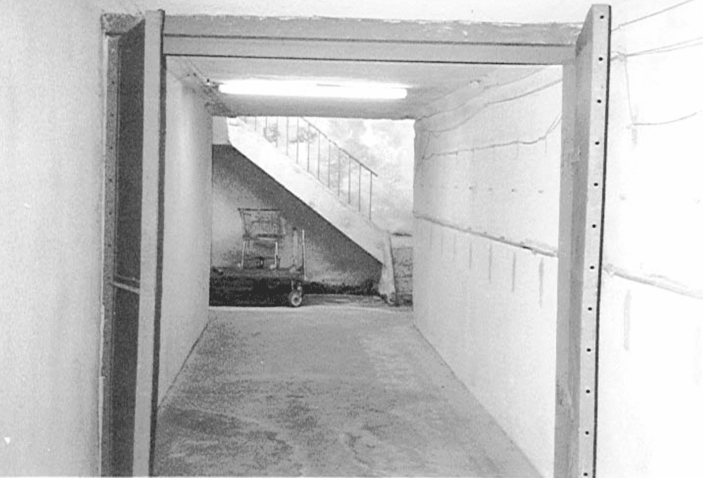
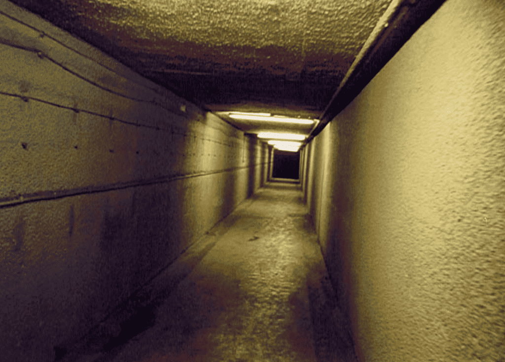
Having bought the site in 1965, the owner held a number of charity balls and also leased out part of the bunker for secure document storage. These days it is completely abandoned and kept secure because of the potential dangers. The length of the tunnel is exaggerated by the lighting and the lack of visual clues. Even from halfway down it still seems to stretch on for ever and evokes just the right atmosphere for such a visit..
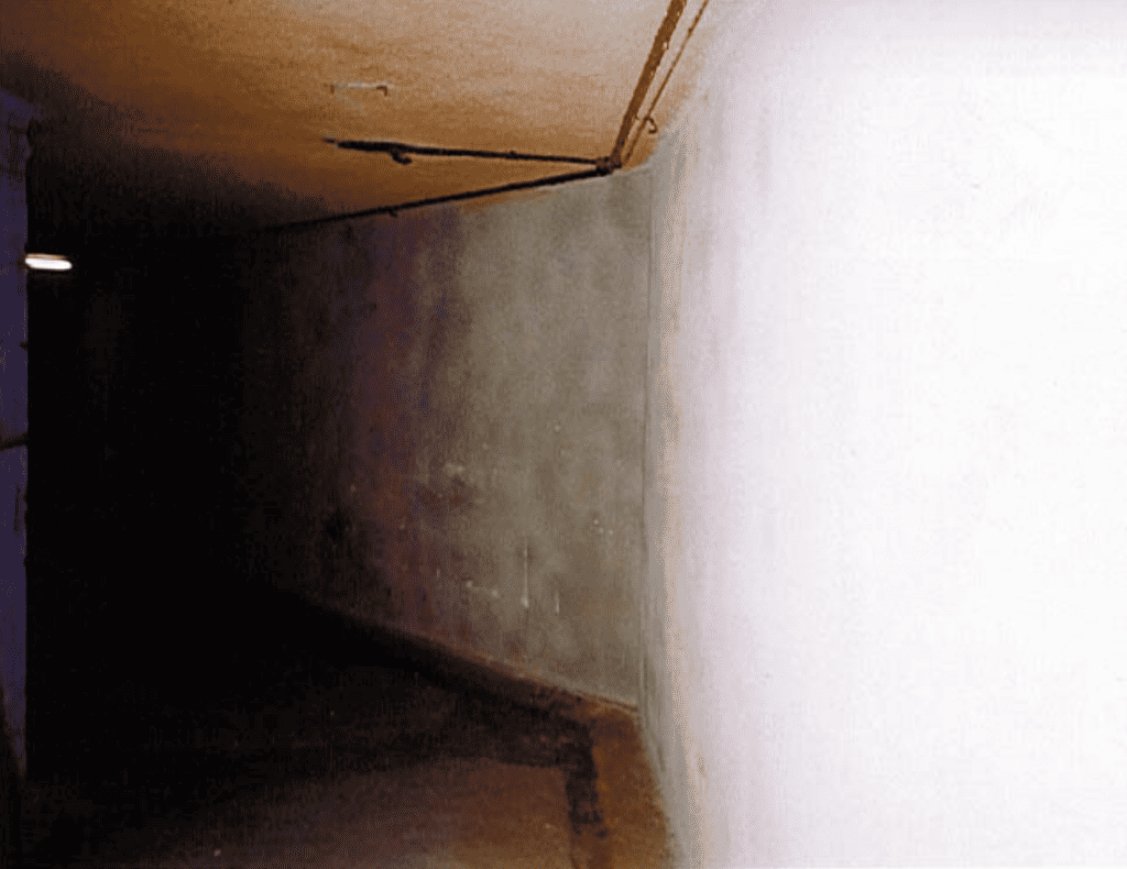
At the end of the corridor is a dog-leg to the left then a short corridor leading to another set of security doors. The tunnel slopes gently downwards throughout its length and ends up some 50 feet below the ground above. The length of the tunnel and the dog-leg would serve to dissipate much of the energy of any blast wave that entered it thus offering protection to the operational parts of the bunker.
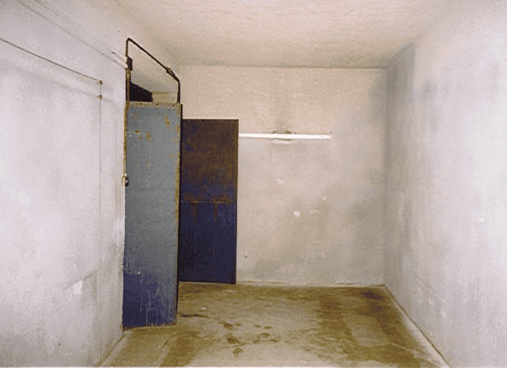
Although not meant to be blast-proof the doors at the end are extremely strong and would withstand a great deal of force. They would certainly resist the efforts of interlopers attempting to gain unauthorised access. At first glance they are similar to the first set, at the start of the tunnel but they are much stronger. At least one opinion is that these were not part of the original installation and were added after the bunker became operational. Alternatively, they may have been added after the bunker was abandoned by the RAF but this not very likely.
The doors are, in fact, doubled up. Inside the first set are a second pair and, when all were closed they they would resist all but the severest force. There are no handles on the outside but there are bars on the inside that fit into the floor. The outer doors also have a couple of welded hasps on them indicating that they could be locked from the outside if necessary but, again, it is difficult to tell if these are a later addition. In any event, they are a massive ‘overkill’ if their only purpose was to keep out casual intruders.
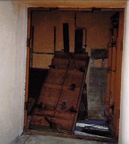
Blast Doors
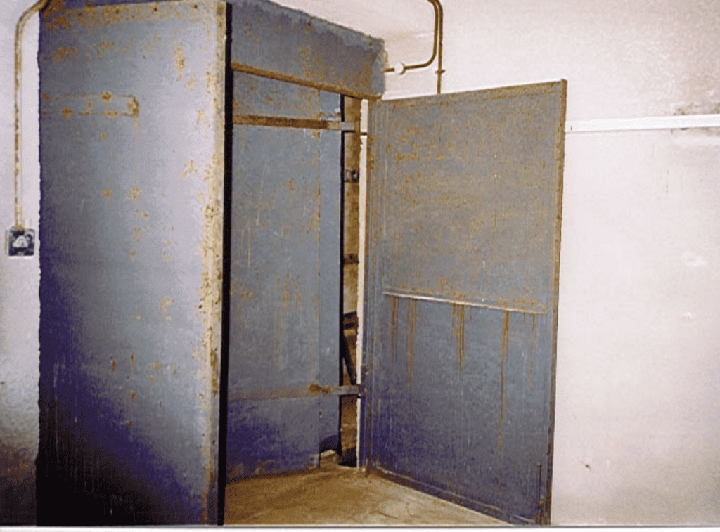
The blast doors were made out of tank metal and are very heavy, some estimates put it as high as a ton and a half. Several layers of metal were hammered together to give protection against blast weapons. They have numerous ‘dogs’ to secure them in place and, in combination with the length & shape of the tunnel, the other doors and their own obvious strength they would have resisted extreme force. The doors are fitted with a flexible sealing material and would have been airtight when closed. The whole installation was designed to withstand the nearby detonation of a 20 kiloton atomic bomb, a typical load for a weapon of that time.
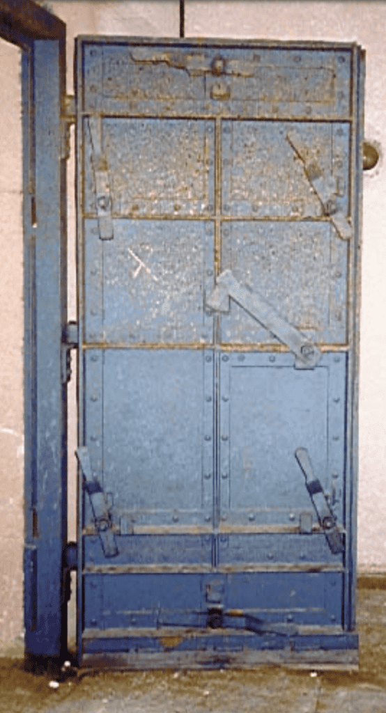
A closer look shows up more detail. The dogs can clearly be seen and the sealing strip can just be made out. The materials used for the sealing strip were claimed to be improved by the application of heat and pressure and the result was meant to be proof against gas and radioactive particles. The doors open outwards because, of course, any over-pressure was expected to come from outside. This would act to close the doors more firmly against the frame and improve the sealing effect. There seems to be no facility to open these from the outside once the locking dogs are in place. Access would only have been with the assistance of those already inside. The doors still move quite freely on their hinges but the inertia makes it hard work and care is needed not to be hit by one when moving it. In normal operation, the whole of the bunker was operated at slightly greater than atmospheric pressure to prevent the accidental intake of any unwanted gasses etc other than through the air filter described later.
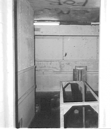
First Chamber
Inside the security doors is the outer chamber of the bunker with the main blast doors at the end. At this point the full strength of the bunker has still not been reached but the walls are still about 10 feet thick. Inside, on the left of the chamber is the transformer room. This supplied the electrical power to the bunker and the equipment beds still remain. All the plant has long gone as has all other equipment of any value. The normal supply from Steyning was backed up by a stand-by emergency generator. This was an 11Kv unit hidden lower down the hill in a low-lying area, next to a small wood, at Erringham Farm. Some four miles of high voltage electrical cable and a 20-pair telephone/control cable were laid along the side of the road up to Truleigh Hill. The Type 14 radar equipment required a rather unusual power supply, 180v AC at 500Hz, in order to drive the equipment at the right frequency.
On the other side of the chamber is the cable inlet duct with cable ties all down it and access to the under-floor cable ducts. The actual floor is, in most parts of the bunker from here on, about four feet below the walkway and is a potential hazard to the unwary. Although most of the floor panels are still sound there are some missing and some are beginning to show their age. Looking upwards towards the inlet there are a number of cable ties and the duct can be seen to split in two. The bends and twists between here and the surface would help dissipate any blast effects from the surface.
The floor of the duct has a machine bed for equipment and also gives access to the under-floor cable runs. This could also serve as an emergency exit. It was possible, just, to climb up the cable runs and round the various twists a and turns to the surface. The exit was covered by a heavy manhole but the site of this has not yet been pinpointed. The mains and radar feeder cables would be brought to the entry by underground runs.
The short corridor inside the blast doors leads to the main bunker corridor.
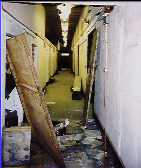
Once round this bend, the main operational part of the bunker is revealed. The central corridor runs the whole length of the operational part. On the left is the main operations room and on the right are a number of smaller rooms. These include a smaller operations room, some domestic accommodation and some store rooms. Also on the right, above the rooms, is a storage loft. The ceilings are mainly about 14 feet high, or 18 feet where the walkway is missing. On the right hand side the ceilings are much lower to allow for the storage space above. The whole of this part of the bunker is encased in 10 to 14 feet of reinforced concrete and it is the strongest part of the whole structure. The origins of the fan mounted on an angle-iron frame are unknown but it might have been part of some original internal circulation system.
Looking back from the opposite end, the storage loft aove the domestic rooms is more clearly seen as can the entrances to some of the smaller rooms. Even some of these had very strong doors fitted. Parts of the ceiling have fallen in at this point and other parts are very loose. It seems pointless but, as can be seen, many of the doors have been removed from their frames and left propped up in the corridor. It is not known whether this was done to make stripping equipment out easier or just some act of vandalism by those who broke in when the site was less secure.
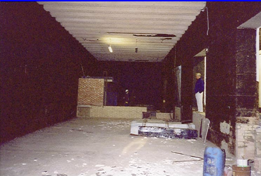
Main Operations Room
This room would once have housed the main radar equipment. (sic see Roy Taylor’s book for detail of the layout). A top secret document (AIR 8/1630) dated 1952 describes some of the equipment installed here. It was a 10cm Chain Home Extra Low (CHEL) installation “designed to provide cover against low flying aircraft and surface vessels”. The main displays specified for similar sites would have been five Plan Position Indicators very similar to those used during the war but it is thought that only one may have been used at Truleigh. These had two cathode ray tubes , one was a range indication only but the other gave a two dimensional representation of the transmitter beam and the target similar to those seen in modern displays. In many cases, and probably here at Truleigh, the delay in producing new PPIs meant that WW2 equipment was refurbished and put back into service. Completion of the Truleigh Hill ROTOR site was expected to be by December 1952 but there were to be delays. Eventually however, in another classified document CRPC/G.391/1831 dated 1/7/53 it was reported that Phase 2 of ROTOR, which included Truleigh Hill, was completed in the last week of June 1953. Hopton was the last station to be handed over to the RAF, delayed as a result of a fire, in January of that year, in the air conditioning plant. This fire was kept secret and no report of it ever reached the public yet the UK’s early warning system was compromised for six months as a result.
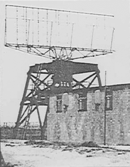
The Type 14 radar used at Truleigh had no height finding unit but, since it was meant to detect low-flying intruder or surface ships, this was not really necessary. The aerial was a basic parabolic aerial mounted on a cabin. The whole of this was mounted on a base unit, described later, and the combined cabin and aerial rotated. Operators or maintenance engineers could actually work within the cabin while it rotated. There were no radar screens or such inside the cabin, of course.
The Air Ministry estimated that the works programme for the 38 radar stations and 4 Sector Operations Centres (SOC) would require 350,000 tons of cement and 20,000 tons of steel amongst other things. The communications side would require some 1,000 miles of new trunk ducts, 750 teleprinters and 40 new repeater station. The majority of this had to be constructed in remote areas and at a time when everything was in very short supply. as well, the whole project was secret and the public were not even to know of its existence.
The layout of this room shows that this was an R2 bunker. R1 and R2’s were both single level with the difference that the R1 bunkers had a 20 foot deep pit in this room where a Kelvin Hughes projector would be sited. This device was a continuous photographic process which filmed the radar screen, processed the film and projected the image onto a glass screen within a very few seconds. Originally there would have been a full height wall where the plant rooms can be seen at the far end and another full height wall some 12 feet further in from that. The room between these two walls was used by the radar service engineers for repairs and testing but there remains no real evidence of either wall. The main operations room is about 90 feet long and all the false floor has been removed and was sold off before the bunker was disposed of by the RAF. At the far end can be seen the three plant rooms with a machine bed in front.
The height of the false floor can be clearly seen in the different floor levels in the corridor and this room. As a standard CHEL station there should have been 5 PPIs installed plus all the associated control and electronics equipment to support it all. Also in this room was a large plotting table reminiscent of the scenes in so many WW2 films. Markers would be placed on the table and moved around as the operators tracked targets both in the air and on the surface above.The RAF recovered all radar equipment and the Ministry auctioned off everything else before offering the site for sale to the public in 1965. Other documentation recently made available contradicts this and different figures of 6 and 8 PPIs have also been found. Memories of those who worked here have faded, of course, so a definitive figure is still sought.
This large room was the scene of the charity balls held in the 1960’s but they were stopped because participants couldn’t be trusted not to smoke. The cladding includes a mixture of cork and pitch and once ignited, would smoulder and burn for weeks. Other sites which have suffered such fires have been rendered completely unusable. Much of the cladding is now detaching itself from the walls and ceilings and the floor is littered with debris in some places.
Plant Rooms
The plant rooms at the far end of this large room are very sturdy and, being inside the bunker, are obviously designed to protect the occupants from fire or other hazards arising from their use. The base of what was once a full-height wall can be seen as can the cable access and ventilation holes.
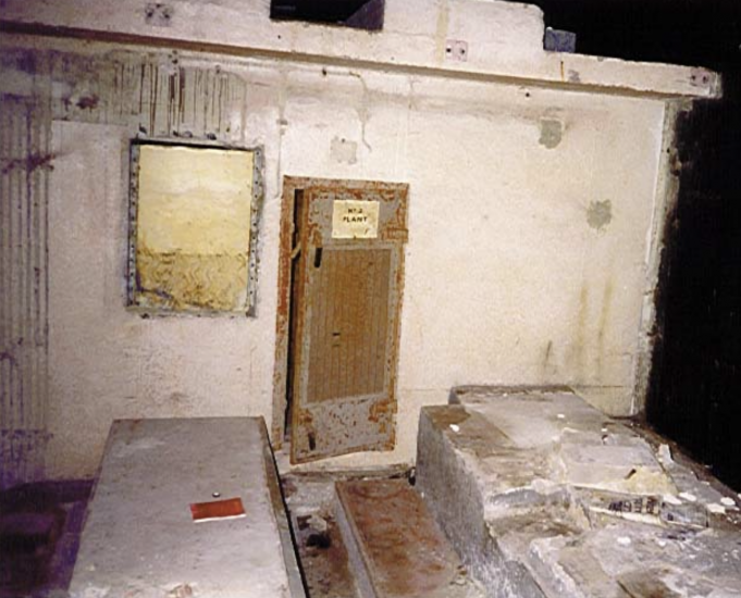
The left-hand room, No 3, housed the air circulation fans used to cool the equipment in the main operations room. The units there generated a great deal of heat so all air circulated in the bunker was first cooled then mixed in the ratio of about 1 part re-circulated to 2 parts fresh before being moved around the rest of the bunker. The middle room, No 1, housed the fan which circulated air around the rest of the bunker but the third plant room remains a mystery. None of the maintenance engineers interviewed can remember what it was used for but the best guess is that it was a spare, stand-by, circulating fan. The concrete beds in front of the doors supported large water tanks which were part of the air cooling system for the air circulating system. The doors seen here are heavy steel and the overall structure is very strong indeed.
The machine bed outside plant room 2, the right-hand one, was used for housing the compressors that ran the refrigeration part of the air conditioning..
Ancillary Rooms
On the right-hand side of the corridor on entry is a smaller room. This is completely bare and, as with the larger room, the raised flooring was completely stripped and sold off. No definitive use for this room has been uncovered and, again, those who did work here cannot give a consistent explanation. The more likely of the explanations heard so far is that it was the Interception Cabin and it was here that the operators sat at their consoles tracking aircraft and practising their interception procedures. The information gained from this would be passed on to the plotting table in the room opposite and on to the Sector Operations Centre.
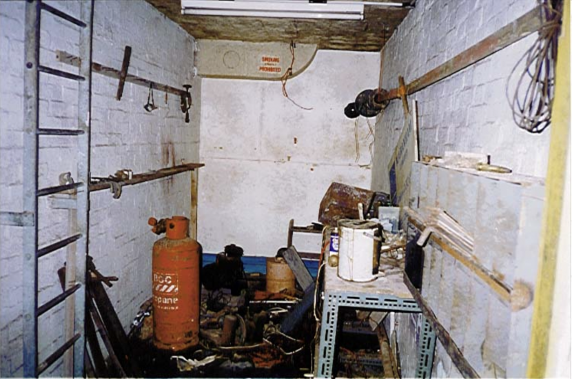
Next door is another, much smaller, room which has recently been used as a workshop – probably by the electricians who re-wired the bunker. It has an access ladder to the above ceiling storage loft and was probably a storeroom of some kind. Similarly, the use for the space above the domestic rooms has not been identified yet. Next along the corridor is the set of rooms that constitute the domestic accommodation.
Domestic Accommodation
No evidence of any sleeping accommodation exists but rest rooms, toilets and a kitchen are there. Conversations with operators on other such sites indicate, however, that it would be a rare installation that didn’t have a standard pattern RAF bed sneaked in somewhere. There are two sets of toilets and two rest rooms connected by a small kitchen. The people manning the station lived in a small domestic site at Stony Lane, Shoreham and were driven in each day to work.
One amusing, and embarrassing, incident arose when a US Congressman revealed that, due to a shortage of trained manpower, the stations were only being manned from dawn to dusk, Monday to Friday. Since the whole ROTOR project was classified Top Secret and was considered to be a major part of the West’s deterrent system there were a lot of diplomatic problems as a result.
The first room is the male toilets, still complete with all the original fittings. The division between Officers’ and Other Ranks’ facilities isn’t obvious at this stage.
On the floor is a tea-chest full of old pianola rolls. Some are still in perfect condition even with their seals still intact. Many are decaying badly however where some water has been spilled on them.
Adjacent to the toilets is the, larger, female rest room. This is a pleasantly large room and would have been quite well used. Fatigue was an ever-present problems for the screen operators, who had to take regular breaks, and it was an awfully long walk to get to anywhere else. The ‘en-suite’ facilities round the corner to the right are also still in pretty good condition.
The small kitchen is between the two rest rooms. Everything except the sink and the extractor hood have been removed. Access to the first rest room is via the doorway at the rear and there is a hatch connecting to the second rest room. The size precludes any large scale catering but, since the normal crew would only have been 10 or so, there was no real need for it. Regular brews and light meals would have been more appropriate since not everyone could be free at the same time.
The male rest-room is smaller and has access to the kitchen via a hatch in the wall. It is interesting to note that the females have a full doorway to the kitchen – perhaps it was assumed that the majority of the work done there would be done by them. In fact, the majority of reminiscences have an airman acting as tea-boy most of the time.
The other two rooms at the end of the central corridor are quite bare except for large amounts of rubbish and debris. This all seems to be left from the time when the bunker was used to store documents etc and none of it seemed to have any connection with the operational times. No photographs are provided since they give no useful information.
The final room is now known to have housed the electrical switch-gear and fuse/circuit breakers etc for the internal electrical supply but nothing remains and the rubbish obscures any useful signs of fixtures and fittings.
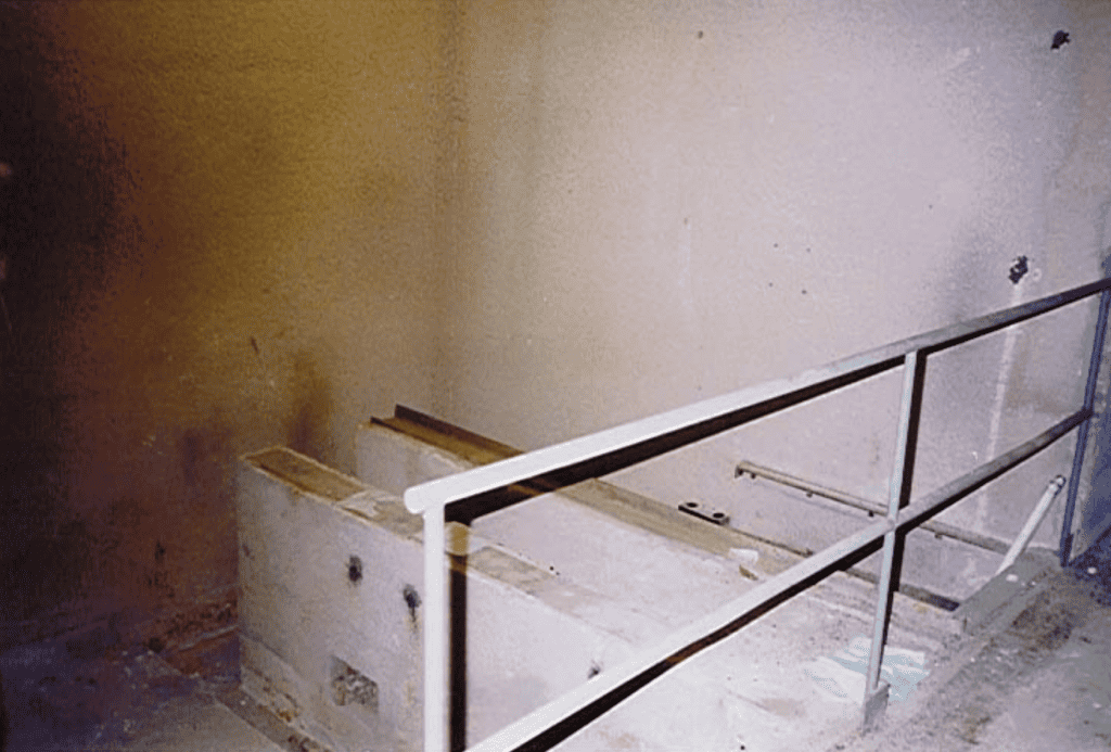
Outer Chamber
On the left of the corridor is the air conditioning plant room. This would have humidified the incoming filtered air and acted as a heat exchanger. All the equipment has been removed from this part of the building but the supporting structure remains. Pipes for carrying the cooling water can still be seen but nothing else remains other than the main supporting structure. The source of the bed spring isn’t known but there was the odd piece of evidence of people using this outer chamber for ‘amusement’ in the days before it was finally sealed again. It certainly doesn’t fit the description of a standard pattern RAF bed.
The foul air extracted from the bunker would pass through this room and on via ducting to the surface. Above, the ducts have been covered by concrete slabs but these are now becoming unstable and, from above, a long drop into the start of the ducts offers yet another danger for the unwary. As can be seen in the photograph, parts of the earth cover are also showing signs of subsidence at the edge of the duct and the once level slabs are now uneven. as a result.
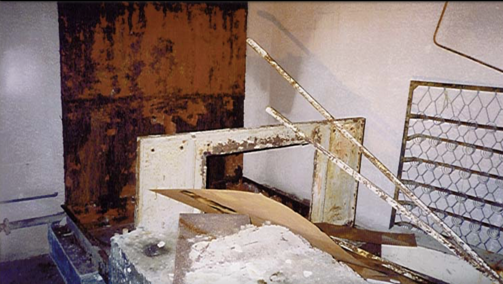
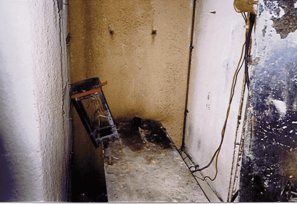
Exit Shaft
At the far end of the bunker, round a bend to the right, are the other set of blast doors. These are of similar construction to the main doors but they have been damaged and one now rests precariously against the wall. When the bunker was abandoned it was left sealed against intruders but a group of youths decided to force an entry. Over a period of time they smashed their way in through the emergency exit (see later) through a makeshift inner security door. When confronted with the blast doors they worked extremely hard at cutting one set of hinges away. One of them was crushed to death in the attempt when the door finally fell free. (sic death occurred 1971, youths reported from Henfield.)
The false floor is missing in places at this point and the under-floor cable ducts can be seen clearly. Great care is needed negotiating this area since it is quite easy to step on an unsupported tile and fall through. Also the locking dogs on the remaining door.
Round the corner, and outside the protection of the main bunker, is the emergency exit, air intake shaft and some more plant rooms. At the end is the emergency exit staircase leading up the air intake shaft to the surface. The panelling at the side of the stairs is made up from parts of the ventilation ducts stripped from the interior of the bunker. A make-shift door is also present and this was, presumably, meant to keep out casual visitors. (sic: 2023 now securely bricked up)
Air Filter Room
The air filter room is next door to the air conditioning room and would clean up the air as it entered the installation. At least one large fan would draw the air in through the air intake at the top of the emergency exit and filter out any radioactive or other pollution before passing it on to the air conditioning unit. Plans were drawn up for the air filters to extract poison gas as well as particles but the delay in developing suitable filters meant that these were never actually installed. In emergency use the system was expected to be able to do a complete air change in the bunker every 10 minutes or so. The filter plant is no longer evident but there is a filter pack still under the floor.
Conclusion
In spite of the extremely high priority given to the ROTOR project, the whole scheme was superseded only a few months after it was begun. Two developments made the whole scheme redundant.
The Soviets developed the Hydrogen Bomb, making the hardened installations built up to that time useless, and the new ‘Type 80’ radar was developed. This new radar was such an advance that a few sites round the country replaced the dozens of ROTOR sites. It also meant enormous cost savings in terms of people, plant, sites etc so, only a few year after it was completed, Truleigh Hill’s Cold War usefulness came to an end.
By 1957 the whole site was all but cleared and in 1965 it was returned to private ownership.
© 1998 Howard Toon
Additional notes and photos added 2023 by www.shorehambysea.com
Site plans:
Click here for site plans of the bunker and bungalow alongside Then & Now aerial views.

Editor’s Note
As at 2023 the Truleigh Hill site and bunker remains in private ownership. Many buildings are still operational for BT use. Entry to underground facilities are secured and bricked up. There are significant hazards within the site. Attempting to access the buildings is trespass and not advised.
A WONDERFUL RECORD- WELL DONE. i WAS AT TRULEIGH HILL FEB 1957 TO jAN 58 i WAS WITH THE BURY HILL VHF D/F FIXER CREW- CAN’T REMEMBER MANY NAMES NOW BUT DO REMEMBER A VERY HAPPY TIME THERE BEFORE I WAS MOVED ON IN THE SOUTHERN SECTOR FIXER GROUP. SUMMER 58 THE WEATHER WAS GOOD THE FOOD WAS GOOD AND THE PALS WERE GOOD AND SHOREHAM BEACH WAS GOOD. LONG TIME AGO NOW.